Installing IMU in Jetson
The Pololu MinIMU-9 v2 is an inertial measurement unit (IMU) that packs an L3GD20 3-axis gyro and an LSM303DLHC 3-axis accelerometer and 3-axis magnetometer onto a tiny 0.8” × 0.5” board. An I²C interface accesses nine independent rotation, acceleration, and magnetic measurements that can be used to calculate the sensor’s absolute orientation. The module includes a voltage regulator and a level-shifting circuit that allows operation from 2.5 to 5.5 V.
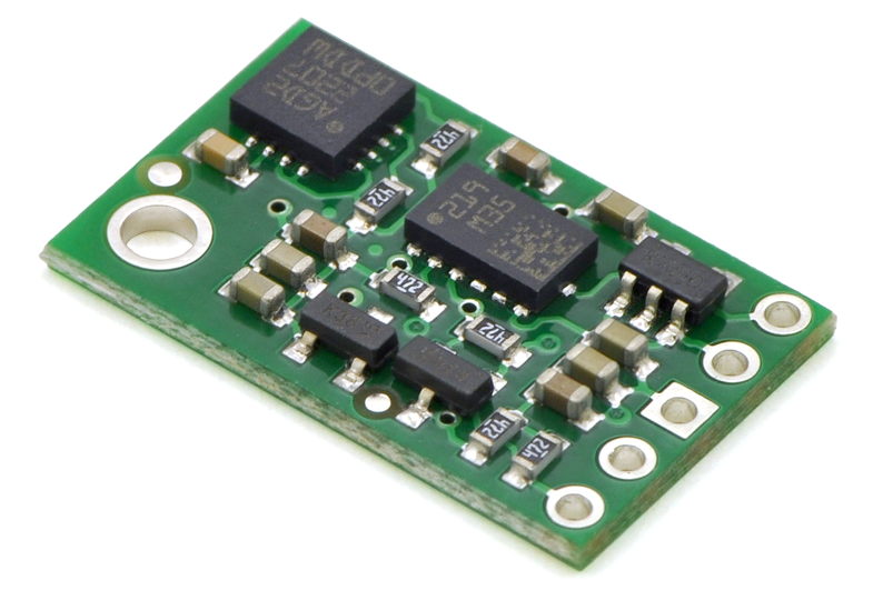
The L3GD20 and the LSM303DLHC have many configurable options, including dynamically selectable sensitivities for the gyro, accelerometer, and magnetometer, as well as a choice of output data rates for each sensor. The two ICs can be accessed through a shared I²C/TWI interface, allowing all three sensors to be addressed individually via a single clock line and a single data line. The nine independent rotation, acceleration, and magnetic readings (sometimes called 9DOF) provide all the data needed to make an attitude and heading reference system (AHRS). With an appropriate algorithm, a microcontroller or computer can use the data to calculate the orientation of the MinIMU board; the gyro can be used to very accurately track rotation on a short timescale, while the accelerometer and compass can help compensate for gyro drift over time by providing an absolute frame of reference. The respective axes of the two chips are aligned on the board to facilitate these sensor fusion calculations.
Specifications
|
Pinout
| PIN | Description
|
|---|---|
| SCL | Level-shifted I²C clock line: HIGH is VIN, LOW is 0 V
|
| SDA | Level-shifted I²C data line: HIGH is VIN, LOW is 0 V
|
| GND | The ground (0 V) connection for your power supply. Your I²C control source must also share a common ground with this board
|
| VIN | This is the main 2.5 – 5.5 V power supply connection. The SCL and SDA level shifters pull the I²C bus high bits up to this level
|
| VDD | 3.3 V regulator output or low-voltage logic power supply, depending on VIN.
When VIN > 3.3 V, VDD is a regulated 3.3 V output supplying 150 mA to external components.
Never supply voltage to VDD when VIN is connected, and never supply more than 3.6 V to VDD.
|
Connecting IMU to Jetson
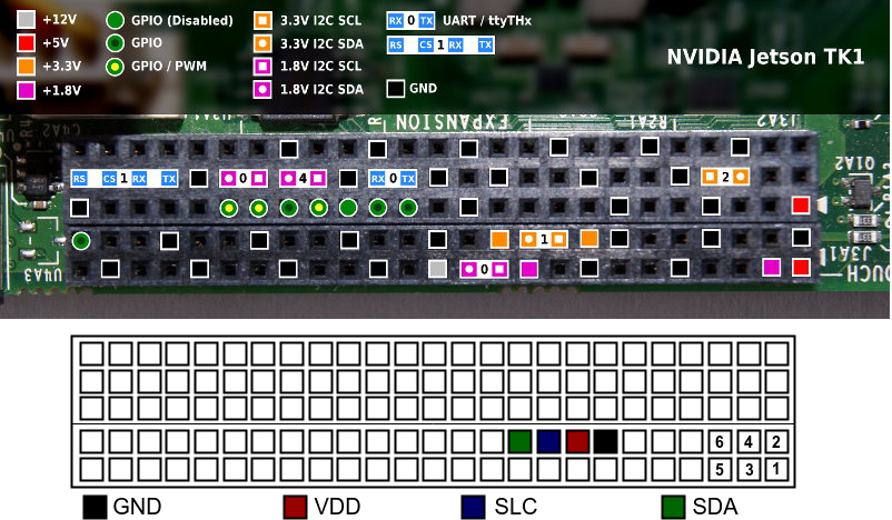
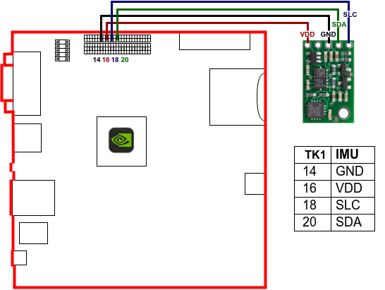
Initially, we have to phisically connect the MinIMU-9 to the Jetson board. We connect the IMU in the Jetson via I²C pins of the board [1]. As presented in the image below, we use the pins: 14 to GND, 16 to VDD, 18 to SLC and 20 to SDA.
Installing MinIMU-9 v2
Once the board is wired up, turn the Jetson TK1 on. After physically connecting the MinIMU-9 to the board, we have to install the MinIMU-9 drivers in the SO to have access to all variables. In order to be able inspect the IMU, you may find it useful to install the i2c tools, by running the command:
$ sudo apt-get install libi2c-dev i2c-tools libboost-program-options-dev
To have access to the i2c ports, you have to add the user to i2c group in Ubuntu. Before adding the user to the group, run groups command to check whether the user is not already in the group. In case the user is not in i2c group, run:
$ sudo usermod -a -G i2c $(whoami)
Log off and log in again to perform the modification. You may also add the permissions to i2c access by adding the line KERNEL=="i2c-[0-7]",MODE="0666" to the file /etc/udev/rules.d/90-i2c.rules.
Next step consists of installing the minimu9-ahrs program that can read data from IMU. In order to install minimu9-ahrs run:
$ git clone https://github.com/DavidEGrayson/minimu9-ahrs.git
$ cd minimu9-ahrs
$ make
$ sudo make install
After compiling and installing minimu9-ahrs you can run the program by typing:
$ ./minimu9-ahrs -b /dev/i2c-1
where -b selects the i2c port being used. The default I²C bus used by minimu9-ahrs program is /dev/i2c-0. As we use a different bus, we have to make a configuration file in our home directory named .minimu9-ahrs with a single line in the form i2c-bus=BUSNAME, where BUSNAME is the full path to the bus we use. Thus, run:
$ echo "i2c-bus=/dev/i2c-1" > ~/.minimu9-ahrs
Calibrating the IMU
According to David Grayson’s Github page the magnetometer will need to be calibrated to create a mapping from the ellipsoid shape of the raw readings to the unit sphere shape that we want the scaled readings to have. The calibration feature for the minimu9-ahrs assumes that the shape of the raw readings will be an ellipsoid that is offset from the origin and stretched along the X, Y, and Z axes. It cannot handle a rotated ellipsoid. It can be informative to run minimu9-ahrs --mode raw > output.tsv while moving the magnetometer and then make some scatter plots of the raw magnetometer readings in a spreadsheet program to see what shape the readings have.
To calibrate the magnetometer, run minimu9-ahrs-calibrate and follow the on-screen instructions when they tell you to start rotating the IMU through as many different orientations as possible. Once the script has collected enough data, it saves the data to ~/.minimu9-ahrs-cal-data and then runs a separate Python script (minimu9-ahrs-calibrator) to create a calibration.
The Python script previously had a complicated algorithm powered by SciPy that would take about 20 minutes to run and was not reliable. Currently, the script just uses a very simple algorithm that finds the minimum and maximum values of each axis of the magnetometer and uses those as the calibration values. This is probably not the best way to calibrate your magnetometer; there are more advanced ways that might work better.
The minimu9-ahrs-calibrate script saves the calibration file to ~/.minimu9-ahrs-cal. The calibration file is simply a one-line file with 6 numbers separated by spaces: minimum x, maximum x, minimum y, maximum y, minimum z, maximum z. These numbers specify the linear mapping from the raw ellipsoid to the unit sphere.
Checking IMU values
As a test, you can look at the raw readings from the sensors on your IMU to make sure it is OK by running:
$ minimu9-ahrs --mode raw
The output should look something like this:
-1318   -3106   -1801     1896    1219    3679        5      18       3
-1318   -3106   -1801     1898    1200    3681        0      24      -1
-1318   -3106   -1801     1899    1200    3688       15      17       2
-1309   -3105   -1799     1874    1201    3671       17      20      -1
-1309   -3105   -1799     1898    1214    3663       11      15      -2
where the third first values correspond to the X-Y-Z values of the raw magnetometer reading, the next three values correspond to the X-Y-Z values of the raw accelerometer reading and the last three values correspond to the X-Y-Z values of the raw gyro reading.
Installing ROS Package
In order to install the ROS package to access IMU data, first we have to download and install the RTIMULib2 library by running:
$ git clone https://github.com/RTIMULib/RTIMULib2.git
$ cd RTIMULib2/Linux/
$ mkdir build
$ cd build
$ cmake ..
$ make -j4
$ sudo make install
$ sudo ldconfig
Having the RTIMULib2 library installed in the Jetson, download and install the i2c_imu package for ROS by typing:
$ git clone https://github.com/jeskesen/i2c_imu.git
$ mv i2c_imu/ ~/catkin_ws/src/
$ cd ~/catkin_ws/
$ catkin_make
Testing ROS Package
To test the ROS package for IMU, you should call the i2c_imu_auto.launch and check whether the topic /imu/data exists. To do so, run:
$ roslaunch i2c_imu i2c_imu_auto.launch
In another terminal, run:
$ rostopic list
And check the topics that appear.
Calibrating IMU using ROS Package
The calibration needs to be performed by the RTIMULibCal utility provided by the library. In case of calibrating more than one IMU, the name to the calibration file can be passed as argument to RTIMULibCal as:
$ RTIMULibCal jetson_imu
This command will run the calibration program where you can choose for calibrating the following:
Options are:

m - calibrate magnetometer with min/max
e - calibrate magnetometer with ellipsoid (do min/max first)
a - calibrate accelerometers
x - exit

Enter option:
In order to calibrate the magnetometer, press m and the following message appear:
Magnetometer min/max calibration
--------------------------------
Waggle the IMU chip around, ensuring that all six axes
(+x, -x, +y, -y and +z, -z) go through their extrema.
When all extrema have been achieved, enter 's' to save, 'r' to reset
or 'x' to abort and discard the data.

Press any key to start...
Press any key and start to waggle the IMU around, checking on the screen that the values are changing. You can stop when no changes appear on the screen anymore to any position you put the IMU. Then, press s to save the data in the jetson_imu.ini file in the current directory. The next step is to copy the .ini file to the config directory of the package. As we have only one IMU in the Jetson, we can move the file to the .ros package changing its name to the current RTIMULib.ini used by the ROS launch.
$ mv jetson_imu.ini ~/.ros/RTIMULib.ini
Now, when starting the IMU ROS node, the calibration file will be loaded.
References
| [1] | Jetson’s GPIO |